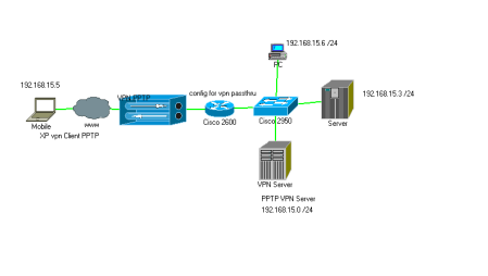
How to configure Cisco 2600 router using dhcp and NAT to allow VPN? (#14347) This is a simple configuration for a Cisco 2600 series router with one interface connected to your ISP using DHCP and NAT, and the second interface connected to your private network. With this configuration remote users can access your private network via a Windows VPN connection.
!
version 12.2
no service pad
service timestamps debug datetime msec
service timestamps log datetime msec
service password-encryption
!
hostname myrouter
!
no logging console
!
aaa new-model
aaa authentication ppp default local
aaa authorization network default if-authenticated
aaa session-id common
!
enable secret 5 XXXXXXXXXXX
enable password 7 XXXXXXXXX
!
username admin privilige 15 password 7 XXXXXXXXXXX
username johndoe password 7 XXXXXXXXXXXXXXXXXX
!
ip routing
ip subnet 0
ip domain-name mydomain.com
ip name-server 192.168.2.1
ip icmp rate-limit unreachable 2000
ip icmp rate-limit unreachable DF 2000
no ip source route
no ip finger
no ip bootp server
no service tcp-small-servers
no service udp-small-servers
no boot network
no service config
!
router rip
version 2
network 192.168.0.0
passive-interface FastEthernet 0/0
no auto-summary
!
!
ip audit notify log
ip audit smtp spam 25
ip audit po max-events 50
ip audit name AUDIT.1 info action alarm
ip audit name AUDIT.1 attack action alarm drop reset
!
vpdn enable
!
vpdn-group 1
accept-dialin
protocol pptp
virtual-template 1
local name my-vpn
!
!
async-bootp dns-server 192.168.2.1
async-bootp nbns-server 192.169.2.1
!
!
interface FastEthernet0/0
description WAN Interface
ip address dhcp
ip nat outside
ip access-group filter_wan_in in
ip audit AUDIT.1 in
no ip unreachables
no ip directed-broadcast
no ip proxy-arp
no ip route-cache
no cdp enable
duplex auto
speed auto
!
interface FastEthernet0/1
description LAN Interface
ip address 192.168.1.1 255.255.0.0
ip nat inside
ip access-group filter_lan_in in
ip access-group filter_lan_out out
cdp enable
duplex auto
speed auto
!
interface Virtual-Template1
ip unnumbered FastEthernet0/1
ip mroute-cache
peer default ip address pool VPN-IN
ppp encrypt mppe 40 required
ppp authentication ms-chap
!
!
ip local pool VPN-IN 192.168.2.51 192.168.2.53
!
ip nat inside source list 1 interface FastEthernet0/0 overload
ip nat inside source static tcp 192.168.1.1 1723 interface FastEthernet0/0 1723
!
ip classless
no ip http server
!
ip access-list extended filter_wan_in
! use this to deny any incoming traffic
permit ip any any
deny ip any any log
!
ip access-list extended filter_lan_in
permit ip any host 192.168.2.51
permit ip any host 192.168.2.52
permit ip any host 192.168.2.53
deny udp any eq 137 any
deny udp any eq 138 any
deny tcp any eq 135 any
deny tcp any eq 139 any
deny tcp any eq 445 any
permit icmp any any
permit ip 192.168.0.0 0.0.255.255 any
deny ip 172.16.0.0 0.15.25.255 any log
deny ip 10.0.0.0 0.255.255.255 any log
deny ip any 192.168.0.0 0.0.255.255 log
deny ip any 172.16.0.0 0.15.255.255 log
deny ip any 10.0.0.0 0.255.255.255 log
deny ip any any log
!
ip access-list extended filter_lan_out
permit ip host 192.168.2.51 any
permit ip host 192.168.2.52 any
permit ip host 192.168.2.53 any
permit icmp any any net-unreachable
permit icmp any any host-unreachable
permit icmp any any port-unreachable
permit icmp any any packet-too-big
permit icmp any any administratively-prohibited
permit icmp any any source-quench
permit icmp any any ttl-exceeded
permit icmp any any echo-reply
deny icmp any any
deny udp any any eq 137
deny udp any any eq 138
deny tcp any any eq 135
deny tcp any any eq 139
deny tcp any any eq 445
deny ip any any log
!
access-list 1 remark NAT Source Restrictions
access-list 1 permit any
!
dialer-list 1 protocol ip permit
dialer-list 1 protocol ipx permit
!
line con 0
password 7 XXXXXXXXXXXXXXXXX
line aux 0
line vty 0 4
password 7 XXXXXXXXXXXXXXXXXXXXXXXXX
!
!
end
The majority of the above configuration is fairly standard and can be found in other FAQs so I will just stick to the settings for getting the router to accept VPN connections.
The first bit:
aaa new-model
aaa authentication ppp default local
aaa authorization network default if-authenticated
aaa session-id common
simply enables the access control model for logins.
username admin privilige 15 password 7 XXXXXXXXXXX
username johndoe password 7 XXXXXXXXXXXXXXXXXX
defines the users and their passwords. These users can log in either over VPN or directly via telnet (or ssh if configured)
vpdn enable
!
vpdn-group 1
accept-dialin
protocol pptp
virtual-template 1
local name my-vpn
this enables virtual private dialup networking (vpdn) using point-to-point tunneling protocol (pptp)
interface Virtual-Template1
ip unnumbered FastEthernet0/1
ip mroute-cache
peer default ip address pool VPN-IN
ppp encrypt mppe 40 required
ppp authentication ms-chap
creates a virtual-template bound to the LAN port of the router and assigns an ip address to the client from the VPN-IN pool
ip local pool VPN-IN 192.168.2.51 192.168.2.53
defines the ip addresses available to the VPN clients (3 in this case)
ip nat inside source list 1 interface FastEthernet0/0 overload
ip nat inside source static tcp 192.168.1.1 1723 interface FastEthernet0/0 1723
defines the static port mappings for NAT 1723 is the port for pptp
The ACLs can be customized to you needs but note how the VPN client addresses are reversed….
–> Fa0/1 In –>
–> Fa0/1 In –>
Now all that left is to configure the client computers. With windows XP it’s easy….
1) open up the Network Connections folder
2) click “Create a new connection”
3) click Next
4) choose “Connect to the network at my workplace” then click Next
5) select “Virtual Private Network connection” then click Next
6) Enter a name for the connection and lick Next
7) Now you can set the VPN connection to auto-dial or not, choose either, then click Next
Enter the IP address of your Router (this is the public address). Since in our case it’s assigned by dhcp we could use a dyndns address here
9) Click Next
10) Click Finish
Once the Wizard has completed right-click the new connection, then click Properties. On the Security tab select “Advanced (custom settings)” and click the Settings button.
Verify that the Data encryption drop-down has “Require Encryption” selected. Then make sure Microsoft CHAP (MS-CHAP) and (MS-CHAP v2) are enabled and click Ok.
Finally goto the Networking tab and change the “type of VPN” from Automatic to “PPTP VPN”, then click the Settings button and verify that:
1) Enable LCP Extensions - is checked
2) Enable software compression - is checked
3) Negotiate multi-link - is not checked
Now your all set and ready to go…..
-b