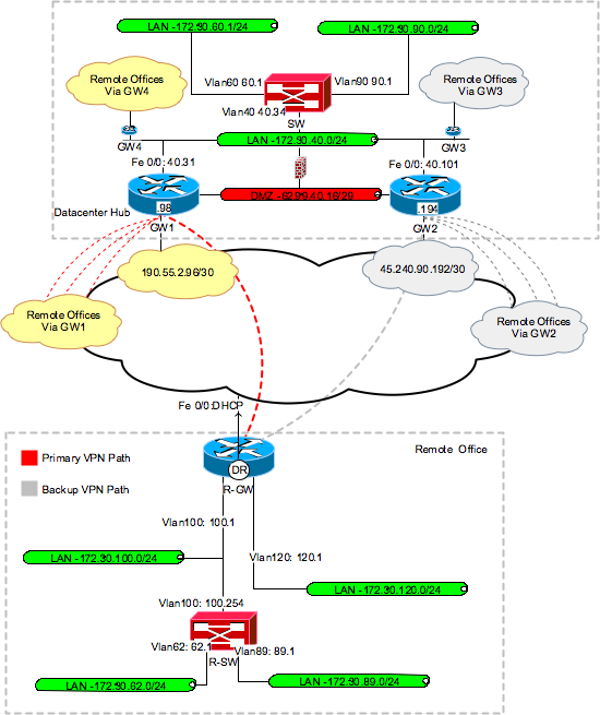
Below is the VPN gateway configuration that supports both of the hardware client examples (the second example elements are in red) we are implementing:
I. AAA configuration:
| GW 1 (Used for topology example 1 and 2) | GW 2 (Used for topology example 1 only) |
aaa new-model
aaa authentication login default local
aaa authentication login userauth local
aaa authorization network groupauth local
!
username outlan-rtr1 password 0 outlan-rtr1
| aaa new-model
aaa authentication login default local
aaa authentication login userauth local
aaa authorization network groupauth local
!
username outlan-rtr1 password 0 outlan-rtr1
|
II. ISAKMP Phase I configuration:
| GW 1 (Used for topology example 1 and 2) | GW 2 (Used for topology example 1 only) |
crypto isakmp policy 10
encr 3des
hash md5
authentication pre-share
group 2
| crypto isakmp policy 10
encr 3des
hash md5
authentication pre-share
group 2
|
crypto isakmp client configuration group
hard-client-fc
key supersecret
save-password
pfs
backup-gateway 45.240.90.2
max-users 1
max-logins 1
!
crypto isakmp client configuration group
hard-client-st
key supersecret
acl hard-client-nets
save-password
pfs
backup-gateway 45.240.90.2
max-users 1
max-logins 1
| crypto isakmp client configuration group
hard-client-fc
key supersecret
save-password
pfs
backup-gateway 190.55.2.98
max-users 1
max-logins 1
|
crypto isakmp profile hard-client
description ISAKMP for Cisco Soft Clients
match identity group hard-client
client authentication list userauth
isakmp authorization list groupauth
client configuration address respond
keepalive 20 retry 10
| crypto isakmp profile hard-client
description ISAKMP for Cisco Soft Clients
match identity group hard-client
client authentication list userauth
isakmp authorization list groupauth
client configuration address respond
keepalive 20 retry 10
|
ip access-list extended hard-client-nets
permit ip 172.30.40.0 0.0.0.255 1.1.1.0 0.0.0.255
permit ip 172.30.40.0 0.0.0.255 172.30.62.0 0.0.0.255
permit ip 172.30.40.0 0.0.0.255 172.30.89.0 0.0.0.255
permit ip 172.30.60.0 0.0.0.255 1.1.1.0 0.0.0.255
permit ip 172.30.60.0 0.0.0.255 172.30.62.0 0.0.0.255
permit ip 172.30.60.0 0.0.0.255 172.30.89.0 0.0.0.255
permit ip 172.30.131.0 0.0.0.255 1.1.1.0 0.0.0.255
permit ip 172.30.131.0 0.0.0.255 172.30.62.0 0.0.0.255
permit ip 172.30.131.0 0.0.0.255 172.30.89.0 0.0.0.255
permit ip 172.30.50.0 0.0.0.255 1.1.1.0 0.0.0.255
permit ip 172.30.50.0 0.0.0.255 172.30.62.0 0.0.0.255
permit ip 172.30.50.0 0.0.0.255 172.30.89.0 0.0.0.255
permit ip 172.30.132.0 0.0.0.255 1.1.1.0 0.0.0.255
permit ip 172.30.132.0 0.0.0.255 172.30.62.0 0.0.0.255
permit ip 172.30.132.0 0.0.0.255 172.30.89.0 0.0.0.255
|
|
III. ISAKMP Phase II configuration:
| GW 1 (Used for topology example 1 and 2) | GW 2 (Used for topology example 1 only) |
crypto ipsec transform-set 3DES-MD5 esp-3des
esp-md5-hmac
| crypto ipsec transform-set 3DES-MD5 esp-3des
esp-md5-hmac
|
crypto dynamic-map hard-vpn-gateway 15
set security-association lifetime seconds 12000
set transform-set DES-MD5
set pfs group2
set isakmp-profile hard-client
reverse-route
| crypto dynamic-map hard-vpn-gateway 15
set security-association lifetime seconds 12000
set transform-set DES-MD5
set pfs group2
set isakmp-profile hard-client
reverse-route
|
crypto map secure-client 10 ipsec-isakmp dynamic
hard-vpn-gateway
| crypto map secure-client 10 ipsec-isakmp dynamic
hard-vpn-gateway
|
IV. Crypto map installation interfaces, Internet policy route and IP routing configuration:
| GW 1 (Used for topology example 1 and 2) | GW 2 (Used for topology example 1 only) |
interface FastEthernet0/0
ip address 190.55.2.98 255.255.255.252
crypto map secure-client
!
interface FastEthernet0/1
ip address 172.30.40.31 255.255.255.0
| interface FastEthernet0/0
ip address 45.240.90.194 255.255.255.252
ip policy route-map int-acc
crypto map secure-client
!
interface FastEthernet0/1
ip address 172.30.40.101 255.255.255.0
|
router ospf 20
log-adjacency-changes
redistribute static metric 200 subnets
network 172.30.40.0 0.0.0.255 area 0.0.0.0
| router ospf 20
log-adjacency-changes
redistribute static metric 200 subnets
network 172.30.40.0 0.0.0.255 area 0.0.0.0
|
ip route 0.0.0.0 0.0.0.0 190.55.2.97 | ip route 0.0.0.0 0.0.0.0 45.240.90.193 |
In order for the remote offices to communicate with each other, the core routers must utilize a dynamic routing protocol to announce the remote networks they have established peering relationships with. This is accomplished using a combination of a dynamic routing protocol, static route redistribution and Reverse Route Injection (RRI). RRI is enabled as one of the crypto map policy options using the configuration command . With RRI enabled, after the client and gateway establish IPsec peering the gateway device dynamically adds static routes to its routing table for the secured network and its associated remote tunnel endpoint. These static routes can then be redistributed via a routing protocol such as OSPF or BGP. In the example above, OSPF redistributes the remote networks.
No comments:
Post a Comment